Classification of Multipliers
1. Array Multiplier
An array multiplier is a digital combinational circuit. It is used to multiply two binary numbers by using an array of full adders and half adders. This array is used for the addition of the various product terms involved at the same time. To form the various product terms, an array of AND gates is used prior to the Adder array. Checking the bits of the multiplier one at a time and forming partial products is a sequential operation that requires a combination of add and shift micro-operations. The multiplication of two binary numbers can be executed with one micro operation with the help of a combinational circuit that forms the product bits at the same time. This is a rapid way of multiplying two numbers because all it takes is the time for the signals to travel through the gates that form the multiplication array. However, it requires many gates. This is the reason it was not economical until the development of integrated circuits.
 |
| Fig. 1: Array Multiplier |
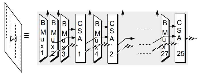
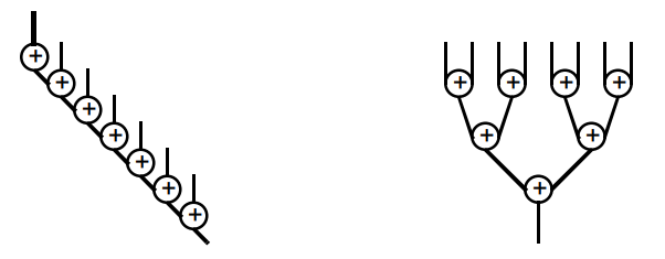
2. Tree Multipliers
The number of partial products can be reduced by tree multiplication algorithm. This can be done by employing multiple input compressors capable of accumulating several partial products concurrently. Tree multiplier can perform the multiplication process for large operands. This is done by reducing the number of partial product bits in a fast and efficient way with the help of a CSA tree constructed from 1-bit full adders.
 |
| Fig. 2: Tree Multiplier |
If the side branches are ignored, one can get 4 inputs in each bit position, and two output at each bit position. This allows us to build binary trees. We can build 3:2 trees, Wallace Trees, which is a little faster, but the wiring is much more complex.
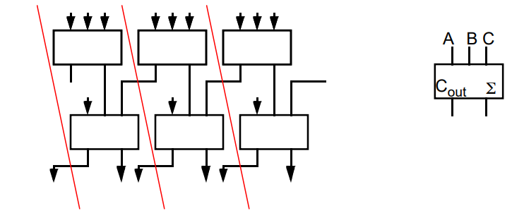 |
| Fig. 3: 4-2 Adder |
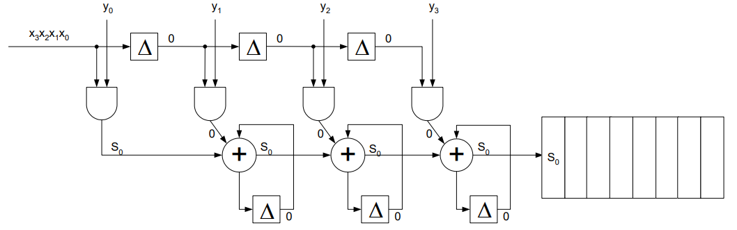
3. Serial Multiplier
The serial multiplier is used where area and power is of maximum importance and delay can be tolerated. This circuit is executed using one adder to add the m*n partial products. The circuit is shown in the fig. below for m=n=4. Multiplicand and multiplier inputs must be arranged in a unique manner synchronized with circuit behavior. The inputs could be presented at different rates. It depends on the length of the multiplicand and the multiplier. Two clocks are used, one for clocking the data and one for the reset. O (m,n) is a first order approximation of the delay. With the following circuit arrangement the delay is given as D =[(m+1)*n + 1 ]*tfa.
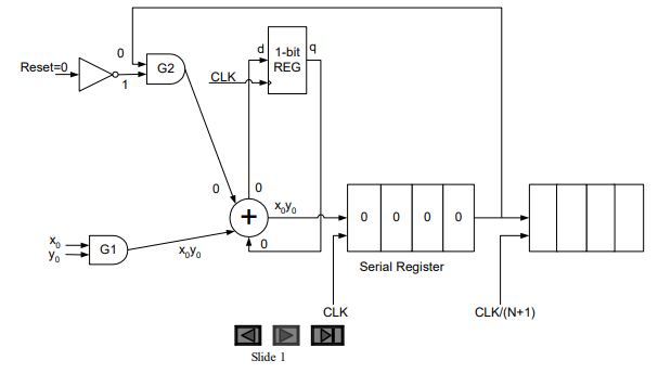 |
| Fig. 4: Serial Multiplier |
4. Serial/Parallel Multiplier
The general architecture of the serial/parallel multiplier is shown below. One operand is fed to the circuit in parallel and the other is serial. N partial products are formed each cycle. On successive cycles, each one does the addition of one column of the multiplication table of M * N PPs. The final results are stored in the output register after M+N cycles. While the area required for M=N is N-1.
 |
| Fig. 5: Serial/Parallel Multiplier |
5. Shift and Add Multiplier
The architecture of the shift and add multiplier is shown in the figure below for a 32 bit multiplication. A value of the multiplicand is added and accumulated, depending on the value of multiplier LSB bit, . The multiplier is shifted one bit to the right at each clock cycle and its value is tested. If it is a 0, only then a shift operation is performed. The multiplicand is added to the accumulator and is shifted by one bit to the right, if the value is a 1. The product is in the accumulator after all the multiplier bits have been tested. The accumulator is 2N*(M+N) in size and initially the N, LSBs contains the Multiplier. The delay is N cycles maximum. This circuit has several advantages in asynchronous circuits.
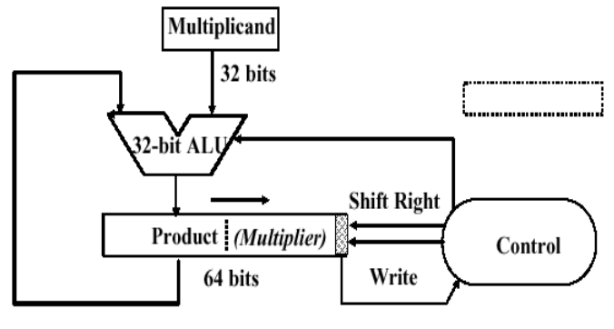 |
| Fig. 6: Shift and Add Multiplier |


Great
ReplyDeleteGreat work 👍
ReplyDeleteThank you !
DeleteGreat work 👍👍
ReplyDeleteThanks Atharva
DeleteNice!
ReplyDeleteThank you
DeleteNice 👍
ReplyDeleteThanks Aishwarya
DeleteGreat
ReplyDeleteThanks a lot Sukhanshu
DeleteNice work...
ReplyDeleteThank you
Deletegreat work!
ReplyDeleteThanks A Lot !!
DeleteVery nicelly written!
ReplyDeleteHope you find it helpful
DeleteWell explained
ReplyDeleteYes, Thank you !
DeleteToo good
ReplyDeleteThank you !
DeleteShort and simple...! Great explanation
ReplyDeleteHope you enjoyed it
DeleteVery informative
ReplyDeleteThanks a lot!
Delete